B-spline elements with immersed boundaries
B-spline approximations have higher order continuity than the Lagrange interpolation that is used in traditional FEM. This implies that if B-spline based shape functions are used, the computed stress and strains will be continuous between elements. Step boundary method is used for applying boundary conditions when B-spline based elements are used for the background mesh. In the traditional recursive definition of B-splines, the parametric domain is subdivided by knots that are represented as and the half-open interval is called the knot span. Uniform B-splines have knots that are equally spaced, so that is constant, to obtain. The B-spline basis function of degree p is defined recursively as follows:
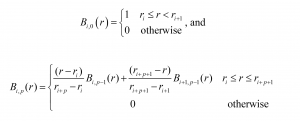
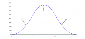
Figure 1 shows the quadratic and cubic B-spline basis functions, defined piece-wise over the domain. The polynomial pieces (B1, B2, etc. in Fig. 1) are defined between the knots such that at the knots they are C1 or C2 continuous.
 |
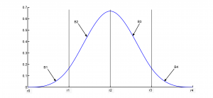 |
| Figure1: (a) Quadratic B-spline basis function | (b) Cubic B-spline basis function |
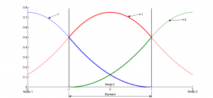
Burla and Kumar [1] developed isoparametric quadratic and cubic B-spline elements by converting the recursive definition of B-splines into parabolic and cubic shape functions respectively. The shape functions of the element are parts of the basis functions of the nodes that overlap within the element as shown in Figure 2. As in traditional isoparametric elements, shape functions of each element is defined in a parametric space where the element length spans the domain [-1,1].
 |
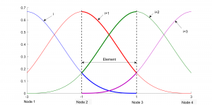 |
| Figure 2: (a) Quadratic B-spline shape functions | (b) Cubic B-spline shape functions |
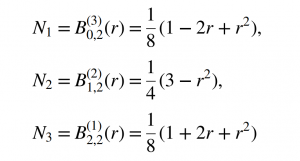
For the quadratic elements, the nodes are located at the mid-point of the elements, i.e., at {-2, 0, 2} in the parametric space. As the basis function of each node extends into adjacent elements, the approximation within each element [-1,1] is controlled by the internal node and the nodes at the center of neighboring elements. The three shape functions for quadratic B-spline isoparametric elements are:
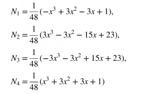
For the cubic elements, the nodes are located at the knots {-3,-1,1,3} in the parametric space. The approximation within a cubic element is influenced by the nodal values of all the corner nodes and the adjacent external nodes. The shape functions for the cubic B-spline element are as follows:
By using a uniform Cartesian mesh, the elements are not distorted and the Jacobian is a diagonal constant matrix. With uniform spacing between nodes, the mapping between the parameter space and the physical space is linear. The shape functions for two and three dimensional quadratic and cubic B-spline elements are constructed as tensor products of one-dimensional B-splines. For these isoparametric elements, the step boundary method has been used to impose boundary conditions [1]. This approach has also been used to implement 3D shell elements [2] that use B-spline shape functions for the approximation of the solution while the geometry is represented as a surface that passes through the elements.
Example: Cantilever beam with circular notch
A simple example of a cantilever beam with circular notch is used below to compare linear, quadratic and cubic B-spline elements. The beam has a thickness of 0.2 m and a uniform shear load of -0.1 MPa is applied at the other end. Figure 3 shows the geometry and the dimensions of the beam as well as the mesh with nodes for the three type of elements. The linear element has nodes only at its corners while the quadratic B-spline element has nodes at the center of the elements. The quadratic 2D element is a 9-node element and the displacement within each element is approximated by values at the center node and the nodes within the neighboring elements. Similarly, for the 16-node cubic element, the displacement is determined by the nodal values of its corner nodes as well as the corner nodes of the neighboring elements. A plot of the computed normal stress in the beam using quadratic B-spline elements is shown in Figure 8.
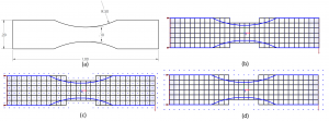
Figure 3: Beam with circular notch: (a) Dimensions, (b) Linear, (c) Quadratic B-spline, and (d) Cubic B-spline elements
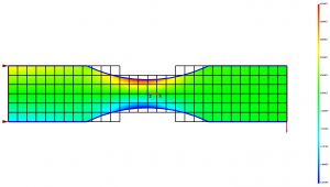
Figure 8: Plot of normal stress in beam with circular notch
Figure 9 shows a log-log plot of the relative error versus the size of the element. The relative error is computed as,

Here uh is displacement field computed using a mesh with element size equal to h and u is the true solution that in this case is the converged solution computed using a high density mesh. The rate of convergence is indicated by the slope of the convergence plot. Slopes corresponding to the quadratic and cubic rates are shown as dashed lines. As seen in the figure, the solution converges at nearly the theoretically expected quadratic rate for linear elements and a cubic rate for quadratic and cubic elements.
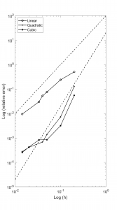
Figure 4: Convergence plot of relative error versus element size
References:
[1] Burla, R., and Kumar, A.V., 2008, “Implicit boundary method for analysis using uniform B-spline basis and structured grid,” International Journal for Numerical Methods in Engineering, 76(13), pp. 1993–2028. DOI: 10.1002/nme.2390.
[2] Periyasamy, P. S. and Kumar, A. V., 2012, “Mesh independent analysis of shell-like structures”, International Journal for Numerical Methods in Engineering,; 91(5), pp. 472-490, DOI:10.1002/nme.4278.